A Reversible DC Motor can turn clockwise or counterclockwise by changing the direction of its torque. In a small permanent-magnet motor, swapping the supply leads usually reverses rotation. The red and black wires change places, and the shaft turns the other way. Simple, but not quite the whole story.
Electrical-machines author Stephen J. Chapman offers a useful foundation in his engineering texts. A concise paraphrase of the principle is: “Reverse the armature current or the field polarity to reverse motor torque.” This distinction matters. In a motor with a wound field, reversing both field and armature currents together may leave the rotation unchanged. Electronic controllers often use an H-bridge to switch current direction without manually swapping wires. The right method depends on the motor’s construction.
This guide explains the motor’s main parts, how current creates rotation, and how reversal works in practical circuits. It also considers speed control, braking, and common mistakes, such as changing direction before a spinning shaft has slowed. A bench motor may reverse in a blink. Its load may not. That detail deserves more attention than it often gets. Understanding the principle helps readers select a suitable motor and controller, interpret wiring diagrams, and test a setup carefully. Exact behavior varies with motor design, load, and controller settings, so a basic rule is not a substitute for the manufacturer’s specifications.
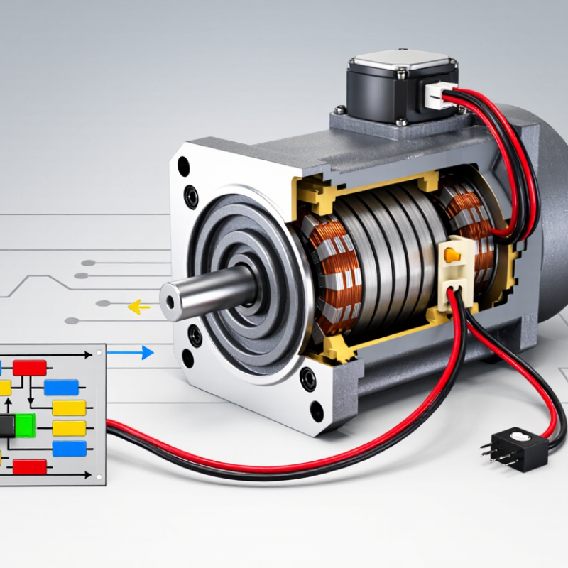
A reversible DC motor is a motor designed to turn its shaft in either direction. Its rotation changes when the electrical relationship between the armature and magnetic field is reversed. In a permanent-magnet motor, this usually means reversing the supply polarity. In a motor with a wound field, the armature connections can be reversed while the field connections stay fixed. Direction changes.
A key feature is controllable forward and reverse motion, useful in small conveyors, powered tools, and positioning mechanisms. Many brushed DC motors can reverse, but the surrounding circuit must make that change safely. An H-bridge circuit, for example, switches current direction electronically. Speed is a separate matter: adjusting voltage or using pulse-width control can change speed, while reversing polarity changes direction. It sounds simple.
The motor’s actual behavior depends on its load, wiring, and control system. A jammed mechanism may draw excessive current, and reversing while the shaft spins quickly can create electrical and mechanical stress. That distinction is easy to miss. In practical setups, operators often pause or slow the motor before changing direction. A motor may be reversible electrically, yet the attached gearbox or machine may not tolerate motion both ways. Check the system, not just the motor label.
A reversible DC motor changes its shaft direction when current polarity is reversed relative to its magnetic field. The stator provides that field, using permanent magnets or field windings. Inside it, the armature, also called the rotor, carries coils that create turning force when energized. The commutator and carbon brushes deliver current to the rotating coils. They also switch the coil connections as the armature turns. Small parts, important work. The shaft transfers rotation to the connected mechanism, while bearings support smooth movement and reduce friction.
Tips: Check the motor’s wiring diagram before reversing its leads. In a typical permanent-magnet motor, swapping the supply wires reverses rotation. Do not reverse both the field and armature connections at once; their relative polarity may stay unchanged. A controller or switch can make direction changes easier, but wiring details vary.
In practice, the motor’s direction is only part of the system. A gearbox, load, or worn brush can affect how smoothly it starts and stops. Listen for unusual scraping, and check that the shaft turns freely with power disconnected. I once treated a motor’s wiring as universal, which was a poor assumption: terminal labels and internal designs differ. Verify the specific motor’s documentation, especially before connecting it to a controller.
| Component or concept | Main function | How it works | Role in reversing rotation |
|---|---|---|---|
| Stator and magnetic field | Provides the magnetic field in which the armature turns. | The field comes from permanent magnets or field windings, depending on motor design. | The field polarity can be reversed in some wound-field motors. For direction reversal, reverse either the field current or armature current, but not both at the same time. |
| Armature (rotor) | Produces torque and rotates inside the stator’s magnetic field. | Current through the armature conductors interacts with the magnetic field to create rotational force. | In a permanent-magnet DC motor, reversing the armature supply polarity reverses the current and usually reverses the direction of rotation. |
| Commutator | Connects the rotating armature windings to the stationary electrical supply through the brushes. | Its segmented copper sections switch the current in armature coils as the rotor turns, helping maintain torque in one direction. | It supports normal commutation; external polarity switching changes the armature current direction relative to the field. |
| Brushes | Transfer electrical current between the stationary circuit and the rotating commutator. | Spring-loaded conductive contacts maintain contact with the commutator while it rotates. | The brushes carry the reversed supply polarity to the armature when the circuit is switched appropriately. |
| Shaft and bearings | Support the rotor and transfer mechanical rotation to the driven load. | The shaft is coupled to the rotor; bearings help it rotate with reduced friction and maintain alignment. | They do not electrically reverse the motor, but they transmit rotation in whichever direction the motor produces. |
| Power supply and terminals | Supply electrical energy to the motor. | The voltage and current available at the terminals determine the motor’s electrical input, within its operating limits. | Swapping polarity at the armature terminals reverses rotation in a permanent-magnet DC motor, provided the motor and circuit are designed for it. |
| Reversing switch or H-bridge | Changes the direction of current through the motor circuit. | A suitable switch or electronic H-bridge changes the connection polarity at the motor terminals. An H-bridge can also support electronic speed control when properly configured. | It provides the command that reverses the armature current relative to the magnetic field. The circuit must be rated for the motor’s voltage and current. |
| Direction of rotation | Describes the motor’s rotational direction as viewed from a specified end of the shaft. | The direction depends on the relative directions of armature current and magnetic field. | Reversing one of these directions reverses the torque and rotation. Reversing both together generally leaves the rotation direction unchanged. |
Note: Always follow the motor and controller wiring instructions. Some DC motor types, including certain series-wound motors, require specific reversal connections.
A DC motor converts electrical energy into motion through magnetic forces. Current flows through the armature windings, creating a magnetic field that interacts with the motor’s permanent magnets or field windings. This interaction produces torque, turning the shaft. In a brushed motor, the commutator and brushes redirect current as the rotor spins, helping maintain rotation. Swap the supply polarity on a permanent-magnet motor, and the shaft usually turns the other way.
The simple explanation can be misleading. Friction, load, and voltage drop all affect real-world speed and torque. A U.S. Department of Energy industry sourcebook reports that motor-driven systems use about 69% of industrial electricity in the United States. That figure covers many motor types, not reversible DC motors alone, but it shows why efficient operation matters. Reversing direction does not automatically improve efficiency; the motor and control must suit the load.
Tips: Use a rated reversing switch or H-bridge, and check the motor’s current limits. Disconnect power before changing wiring. If direction changes under load, expect a jolt; the mechanism may need a gentler stop.
Source: U.S. Department of Energy, Improving Motor and Drive System Performance: A Sourcebook for Industry, 2nd edition.
A reversible DC motor can turn clockwise or counterclockwise when its electrical connections or control signals change. In a brushed, permanent-magnet motor, reversing the supply polarity usually reverses rotation. The rotor’s current changes direction, while the magnetic field remains fixed. Simple, but not every DC motor works this way.
One method uses a DPDT switch or relay to swap the two supply wires. For electronic control, an H-bridge changes current direction without moving wires. This is common in small robotic drives and powered mechanisms. A wound-field motor needs more care: reverse the armature connections or the field connections, but not both. Reversing both can leave the rotation unchanged. Brushless DC motors also need a compatible controller; swapping their supply wires alone may not reverse them. A frequent workshop assumption is that every motor reverses by swapping leads. It’s an easy mistake.
Tips: Stop the motor before reversing direction when possible. Sudden switching can create high current and stress gears or couplings. Check the motor’s wiring diagram, and test with the shaft unloaded. A little caution saves parts.
A reversible DC motor can rotate its shaft in either direction. In many designs, reversing the supply polarity changes the rotation. Some systems use a controller instead, especially when smooth starting or speed adjustment matters. Direction matters in adjustable beds, powered vents, small conveyors, and vehicle actuators, where a mechanism must extend and retract or move items both ways.
Choose a motor by matching its voltage and torque to the actual load. Check startup current, operating speed, duty cycle, and whether a gearbox is needed. A motor that moves a mechanism freely on a workbench may struggle once the mechanism carries weight. Also consider mounting space, heat, dust, and how often direction will change. A tidy specification sheet can still miss a real-world detail: friction may rise after installation.
Tips: Test the motor with the intended load before finalizing the design. Confirm that the controller supports reversal and that wiring is protected from loose connections. Add mechanical stops or limit switches where overtravel could damage the mechanism. Keep a little margin; selecting right at the calculated limit can leave too little room for wear or changing loads.
It is a motor that turns its shaft clockwise or counterclockwise. Direction changes when electrical connections or control signals change.
In many permanent-magnet motors, swapping the supply wires reverses current through the armature. The fixed magnetic field then produces opposite rotation.
No. Wound-field motors need specific connection changes. Brushless motors require a compatible electronic controller.
A suitable switch or relay can exchange the supply wires. An H-bridge can reverse current electronically.
Stop it when possible. Sudden reversal can create high current and stress gears, couplings, and shafts.
Check the motor’s wiring diagram and terminal labels. Designs differ. Never assume the connections are universal.
Match voltage, torque, speed, startup current, and duty cycle to the real load. Include space, heat, dust, and gearbox needs.
The installed mechanism may add weight, friction, or alignment problems. A workbench test can be misleading.
Use protected wiring, mechanical stops, or limit switches where overtravel could cause damage. Leave torque margin for wear.
The gearbox, bearings, brushes, load, and controller all matter. Listen for scraping, and turn the disconnected shaft by hand.
A Reversible DC Motor is a direct-current motor designed to rotate in either direction, making it useful wherever motion must move forward and backward. Its main parts typically include a stator, rotor or armature, windings, brushes, and a commutator, which work together to create and guide magnetic forces. When electrical current flows through the windings, the interaction between magnetic fields produces torque, converting electrical energy into mechanical motion.
The direction of rotation can be changed by reversing the current through the armature or, in suitable motor designs, by reversing the field polarity. Reversible DC motors are used in applications such as positioning systems, powered mechanisms, and equipment that needs controlled bidirectional movement. When selecting one, consider the required speed, torque, voltage, operating conditions, control method, and how frequently the direction will change.

WICCA Motor